Thursday, November 24, 2016

How The Boost Converter Works

How The Boost Converters Work

Contributed​ By Imran Ashraf Khan
A boost converter (also called step-up converter) is a DC to DC converter circuit which is designed to convert an input DC voltage into an output DC voltage with a level that may be much higher than the input voltage level.


However the process always conserves the relation P = I x V, which means that as the output of the converter steps up the input voltage, the output proportionately undergoes a reduction in current, which causes the output power to be almost always equal to the input power or less than the input power.

How a Boost Converter Works


boost converter is a kind of SMPS or switch mode power supply which fundamentally works with two active semiconductors (transistor and diode) and with a minimum of one passive component in the form of a capacitor or an inductor or both for greater efficiency.

The inductor here basically is used for stepping up the voltage and the capacitor is introduced for filtering the switching fluctuations and for reducing current ripples at the output of the converter.

The input power supply which may be required to be boosted or stepped up could be acquired from any suitable DC source such as batteries, solar panels, motor based generators etc.
Operating Principle


The inductor in a boost converter plays the important of stepping up the input voltage.

The crucial aspect which becomes responsible for activating the boost voltage from an inductor is due to its inherent property of resisting or opposing a suddenly induced current across it, and due to its response to this with a creation of magnetic field and subsequently destroying of the magnetic field. The destroying leads to the releasing of the stored energy.

This above process results in the storing of the current in the inductor and kicking back this stored current across the output in the form of back EMF.

relay transistor driver circuit can be considered a great example of a boost converter circuit. The flyback diode connected across the relay is introduced to short circuit the reverse back EMFs from the relay coil and to protect the transistor whenever it switches OFF.

If this diode is removed and a diode capacitor rectifier is connected across the transistor's collector/emitter, the boosted voltage from the relay coil can be collected across this capacitor. 


The process in a boost converter design results in an output voltage that’s always higher than the input voltage.

Referring to the following figure, we can see a standard boost converter configuration, the working pattern may be understood as given under:

When the shown device (which could be any standard power BJT or a mosfet) is switched ON, current from the input supply enters the inductor and flows clockwise through the transistor to complete the cycle at the negative end of the input supply.


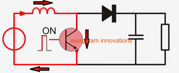
During the above process the inductor experiences a sudden introduction of current across itself and tries to resist the influx, which results in the storing of some amount of the current in it through the generation of a magnetic field.

At the next subsequent sequence, when the transistor is switched OFF, the conduction of current breaks, yet again forcing a sudden change in the current level across the inductor. The inductor responds to this by kicking back or releasing the stored current. Since the transistor is in the OFF position, this energy finds its path through the diode D and across the shown output terminals in the form of a back EMF voltage.


The inductor performs this by destroying the magnetic field which was earlier created in it while the transistor was in the switch ON mode.

However, the above process of releasing energy is implemented with an opposite polarity, such that the input supply voltage now becomes in series with the inductor back emf voltage. And as we all know that when supply sources join in series their net voltage adds up to produce a bigger combined outcome.

The same happens in a boost converter during the inductor discharge mode, producing an output which may be the combined result of the inductor back EMF voltage and the existing supply voltage, as shown the diagram above

This combined voltage results in a boosted output or a stepped up output which finds its path through the diode D and the across capacitor C to ultimately reach the connected load.

The capacitor C plays quite an important role here, during the inductor discharge mode the capacitor C stores the released combined energy in it, and during the next phase when the transistor switches OFF again and the inductor is in the storing mode, the capacitor C tries to maintain the equilibrium by supplying its own stored energy to the load. See the figure below.


This ensures a relatively steady voltage for the connected load which is able to acquire power during both the ON, and OFF periods of the transistor.

If C is not included then this feature is cancelled resulting in a lower power for the load and lower efficiency rate.


The above explained process continues as the transistor is switched ON/OFF at a given frequency, sustaining the boost conversion effect.

Modes of Operation


A boost converter may be primarily operated in two modes: the continuous mode, and the discontinuous mode.

In continuous mode, the inductor current is never allowed to reach zero during its discharging process (while the transistor is switched OFF).

This happens when the ON/OFF time of the transistor is dimensioned in such a way that the inductor is always connected back quickly with the input supply through the switched ON transistor, before it’s able to get completely discharged across the load and the capacitor C.

This allows the inductor to consistently produce the boost voltage at an efficient rate.

In the discontinuous mode, the transistor switch ON timing may be so wide apart that the inductor may be allowed to get discharged fully and stay inactive in between the switch ON periods of the transistor, creating huge ripple voltages across the load and the capacitor C.

This could make the output less efficient and with more fluctuations.

The best approach is to calculate the ON/OFF time of the transistor which yields maximum stable voltage across the output, meaning we need to make sure that the inductor is optimally switched such that it’s neither switched ON too quickly which might not allow it to discharge optimally, and nor switch it ON very late which might drain it an inefficient point.


Calculating, Inductance, Current, Voltage and Duty Cycle in a Boost Converter


Here we’ll discuss only the continuous mode which is the preferable way to operate a boost converter, let’s evaluate the calculations involved with a boost converter in a continuous mode:

While the transistor is in the switched ON phase, the input source voltage (V_i) is applied across the inductor, inducing a current (I_L) build up through the inductor for a time period, denoted by (t). This may be expressed with the following formula:

ΔIL/Δt = Vt/L

By the time the ON state of the transistor is about to get over, and the transistor is about to switch OFF, the current that is supposed to build up in the inductor may be given by the following formula:


ΔIL(on) = 1/L  0ʃDT   

 or

 Vidt = DT(Vi)/L

Where D is the duty cycle. For understanding its definition you can refer to our previous buck converter related post

L denotes the inductance value of the inductor in Henry.


Now, while the transistor is in the OFF state, and if we assume the diode to be offering minimum voltage drop across it and the capacitor C large enough to be able to produce almost a constant output voltage, then the output current () can be deduced with the help of the following expression

Vi   Vo  =  LdI/dt

 Also, the current variations () that may occur across the inductor during its discharge period (transistor off state) can be given as:

ΔIL(off) = 1/L x DTʃT    (Vi   Vo)dt/L = (Vi  Vo) (1 – D)T / L


Assuming that the converter could be performing with a relatively steady conditions, the magnitude of current or the energy stored inside the inductor throughout the commutation (switching) cycle can be assumed to be steady or at an identical rate, this may be expressed as:


E = ½ L x 2IL


The above also implies that, since the current throughout the commutation period, or at the beginning of the ON state and at the end of the OFF state should be identical, their resultant value of the change in the current level should be a zero, as expressed below:

ΔIL(on)  +  ΔIL(off) = 0


If we substitute the values of  ΔIL(on) and  ΔIL(off) in the above formula from the previous derivations, we get:

ΔIL(on)  -  ΔIL(off) Vidt/L + (Vi   Vo) (1 – D)T / L = 0

Further simplifying this yields the following result:
Vo/ V= 1 / (1 – D)

or


Vo  V/ (1 – D)

The above expression clearly identifies that the output voltage in a boost converter will be always higher than the input supply voltage (across the entire range of the duty cycle, 0 to 1)

Shuffling the terms across the sides in the above equation we get the equation for determining the duty cycle in a boost converter working cycle.
D = 1 –  Vo/ Vi

The above evaluations give us the various formulas for determining the different parameters involved in boost converter operations, which can be effectively used for calculating and optimizing an accurate boost converter design.

Buy LCD LED TV Troubleshooting​ Guide eBook By Imran Ashraf Khan.

Sunday, November 20, 2016

Philips 32PFL5237 Sound Problem

Philips No Sound Issue

There are many reasons that will cause such problem. TV Philips 32PFL5237/V7 has pictures but no sound, what to do? In this article, we will tell you how to figure out this problem.
By Imran Ashraf

Step 1: check to see if you mute on. Sometime you may override mute function only by pressing the up or down volume on your remote. Increase volume. See the visual display of sound volume change on the screen to see if it changes when you turn the audio up or down. If not, you have a malfunction remote and you should get a good one to check.
Step 2: check to see if there is any earphones that connect to your Philips 32PFL5237/V7.
Step 3: you should know that when no signal is detected, your Philips 32PFL5237/V7 will automatically switches off the sound. Because this is an appropriate operation, so you can never see any malfunction indication.
Step 4: if you are using a theatre system, you should check to ensure that your speakers and theatre system is not plugged in.
Step 5: check to see if you uses SPDIF connection with external equipment which will only have output with digital channels.
Step 6: for HDMI to DVI connector, DVI does not carry the audio signal. You will need to use a set of Red and White RCA connectors to obtain sound. Connected the audio cables to AV1; set the sound source through Settings menu; select Setup and then Source menu; Press the cursor right to enter the list of types of devices connected to the selected input; select the accessory Analog Audio and you will see a list of connected devices which is automatically detected by your Philips 32PFL5237/V7. Select HDMI from the Analog Audio to active. Then, everything will be all right. Make sure your Philips 32PFL5237/V7 uses the software that posted on the website.
Step 7: If you have in-built speakers and you can see the volumes changes on the screen when you press up and down the volume on remote, then you may have a stuffed speaker or there is problem with your audio circuit.
If you can not have sound through the above-mentioned methods, I mean through settings or remote control check, and then you probably need to have help our expert team members at lcdledebooks@gmail.com
WhatsApp us +923139292880

Wednesday, November 9, 2016

Buying Volume 1 of Lcd Led Panel Failure Bypassing

For the display problems including in this ebook like:

LCD LED TV No Display,
Slow Motion Picture
 Grey Or Black Display,
 White Display,
Screen Double Images,
Display Jumping/Jurking,
 Display Distortion, Ghost 
Display Colour Solution,
Horizontal & Vertical Lines/Bars,
Negative Image 
Solarization Image 
Panel Working Voltages Data
Half Screen Display 
Cof Data and Much Much More


I Want This Ebook! What Do I Do Now?”

It’s easy to order. All you need to do is click on the link below, which will take you to the order page, and then you just enter your information in. The whole process only takes a minute or two. As soon as you have placed your order, you’ll immediately sent you through your email address where you can save the Ebook in your computer. And don’t worry, downloading the information is a real snap. (It works perfectly with both MAC and PC computers.) Also for Laptops , Tablets and Android Phones, There is no shipping and handling because it’s an electronic course. That means you won’t have to wait in order to begin using these strategies in your repair business. You can be on your way to success in just a few minutes. Even if you have never downloaded anything from the internet before, don’t worry, it comes with instructions. It’s so easy! All of the Screen Bypassing TV’s problems and solutions are revealed in a step-by-step, easy to understand format. This info-product is one-of-a-kind and not found in any BOOKSTORES!
Go ahead and click the order link below, and see what all the information is about. You’ll get instant access to the entire course even if it’s 4 am in the morning.

Your One-Time Investment Is

Only $20 USD


After Completing Your Payment We Will Send you Volume 1 With in 2 hours to your email account.

LCD LED Panel Failure Volume 1 Index.

Product Details:E-book Format: Ms Office Doc file (Not a hard copy book)
Pages: over 200pages (+ Bonuses)
File size: 24MB
Language: English
Bonus: Included Email Support and Bonuses of LCD/LED Panel repairing information!
Compatible with: Android Phones, PC, Laptop & MAC Computer
Price: $20 USD (Offer Price only!)
(Orignal price $39.95 USD)

Monday, November 7, 2016

Do It Your Self PC Oscilloscope

Soundcard Oscilloscopedeutsche Version

Front panel of the soundcard oscilloscopeAuthor: Christian Zeitnitz
Main features:
The PC based Soundcard Oscilloscope receives its data from the Soundcard with 44.1kHz and 16 Bit resolution. The data source can be selected in the Windows mixer (Microphone, Line-In or Wave). The frequency range depends on the sound card, but 20-20000Hz should be possible with all modern cards. The low frequency end is limited by the AC coupling of the line-in signal. Be aware, that most microphone inputs are only mono.
The oscilloscope contains in addition a signal generator for 2 channels for sine, square, triangular, sawtooth wave forms and different noise spectra in the frequency range from 0 to 20kHz. The signal can be defined by a mathematical formula as well. The signals are available at the speaker output of the sound card. These can be fed back to the oscillocope in order to generate Lissajous figures in the x-y mode.
Download the latest version: scope V1.46
Obtain a commercial license here
Interested in a customized version?
Support the development of this program by obtaining a private donation license

Additional features

Lissajous figure generated and displayed by the soundcard oscilloscopes (x-y mode)
  • Trigger modes: off, automatic, normal and single shot
  • Triggerlevel can be set with the mouse
  • The signals of the two channels can be added, subtracted and multiplied
  • x-y mode
  • Frequency analysis (Fourier spectrum)
  • Waterfall diagram (frequency spectrum as function of time)
  • Frequency filter: low-, high-, band-pass and band-stop
  • Cursors to measure amplitude, time and frequency in the main window
  • Audio Recorder to save data to a wave file
  • For multi soundcard system, the used card can be selected in the settings tab
The program has been written in LabView (™ by National Instruments). For the actual Sound I/O part the WaveIO package by the same author has been used. 

Signal Sources

The signals for the oscilloscope can be internal to the computer (MP3 player, function generator etc.) or from external sources (line-in, microphone). For external sources care has to be taken, not to exceed the voltage range of the inputs. The range is usually only ±0.7V !! If higher voltage need to be analyzed, a voltage divider has to be used. Additional protection diodes are recommended in order to avoid any damage to the sound card and to the computer. 

Requirements

This program will run on Windows 2000/XP/Vista/7/8 (32bit and 64bit) computers with a sound card. It will not install on older versions of Windows. The speed requirements are not very hard. A 1GHz machine is suffient. On slower CPUs the load on the system might lead to reduced responsiveness of the system.

Terms of usage and licenses

This Software and all previous versions are NO Freeware!
  • The use of the software and of the documentation is granted free of charge for private and non-commercial use in educational institutions
  • Any commercial application requires a corresponding license (see below)
  • Distribution and sale of the program is prohibited. Contact the author in order to obtain a resale license.
If you like to support the further development of this program please obtain a private license by following this link
Commercial usage: In order to obtain a commercial license follow this link
All right reserved.
The signal generator is utilizing.

Downloads

Instructions: The program comes as a self-extracting archive and will start the installation automatically. After the installation start the scope from the entry in the program menu. Enjoy !
Version 1.46
  • Changes
    • Improved mouse control of the amplitude measurement: after the acquisition is stopped (Run/Stop) a right click into the scope window starts the measurements. A left click positions the cursor on the time axis. The left and right cursor keys allow a fine adjustment of the cursor
    • Mouse control of measurement in the frequency window: left click positions the cursor on the frequency axis. Fine adjustment with the left and right cursor keys
    • Expert mode allows to modify the sampling rate within the program and direct access to the configuration file
    • Solved CPU load problem for long time window
    • Memory problem solved
    • One more crash problem solved when running under Windows 2k/XP behoben
  • Version 1.46 of the program (all languages): scope_146
  • Only the englisch manual für Version 1.46
  • License
    • All licenses obtained for previous scope versions are valid for this version as well
    • Private license to support the further development of the program
    • Commercial license for the usage in companies and non-public educational institutions

+Older versions

Final Remarks

The program requires a correctly installed and configured soundcard on your Windows computer. In case of problems consult the manual and the frequently asked question.
If you still have a software related problem send mail to C.Zeitnitz

BUY NOW

LCD LED Tv Panel Bypassing Methods eBooks.

Learn how to repair Panel failures,T-con problem in LCD LED TVs with comprehensive guide line with Schematics and Pictures of Problems, This eBook (PDF) or (Doc)format was written for Advanced Level of Technician of LCD LED and Plasma TV repair and includes many Bypass method. If you want to become expert in this filed of LCD LED TV repair  than this is a good eBook for you. Maybe you have a broken LCD TV sitting at home or your workshop and you want to repair it quickly. No Problem who you are or what your reason is for wanting to repair LCD or LED TVs you have come to the right place.Once you have complete your purchase you will be sent a link to download a copy immediately.
Volume 1 ,
Volume 2 ,
Inverter Bypass eBook,
SMD Data Guide eBook.
E-mail me after you deposit 55 USD with Paypal System.
At lcdledebooks@gmail.com

LCD LED Panel Méthodes Contournement eBooks .
LCD  LED Panel Méthodes Contournement eBooks .
Apprendre à réparer les défaillances du panneau , problème T - con dans TVs LCD LED avec la ligne guide complet avec schémas et photos de problèmes , Cet eBook ( PDF ) ou ( Doc ) format a été écrit pour avancée de niveau technicien de LED LCD et Plasma TV réparation et comprend de nombreuses méthodes de contournement . Si vous voulez devenir expert dans ce dépôt de réparation de TV LCD LED que cela est un bon eBook pour vous. Peut-être que vous avez un téléviseur LCD cassé assis à la maison ou dans votre atelier et vous voulez réparer rapidement. Pas de problème qui vous êtes ou ce que votre raison est de vouloir réparer les téléviseurs LCD ou LED vous avez frappé à la bonne place.Once vous avez compléter votre achat, vous recevrez un lien pour télécharger une copie immédiatement.


LCD/LED पैनल रिपेयर करने केलिए विवरण हमको ब्लॉग में, सर्विस मैन्युअल में, इंटरनेट पे मिलते हे ,लेकिन हमको सभी जगहों पर पहुँच नहीं सकते, हमें एक साथ सभी विवरण मिलता तो बहुत अच्छा होगा,  ebooks of Lcd Led Tv Bypassing Methods में पैनल का बहुत सारा विवरण  दिया हुआ हे,मेरे को यकीन हे ये  हमारे दैनिक जीवन में मदद करेंगे , ये बुक आपको ऑनलाइन पे भी खरीद सकते हो, इसकेलिए आप ये वेबसाइट पे जाने का हे  
  www.electronics-tricks.blogspot.com


പാനൽ നന്നാക്കുവാൻ സഹായിക്കുന്ന ഒരുപാട് കാര്യങ്ങൾ ഇന്റെർനെറ്റിലും ,ബ്ലോഗുകളിലും ,സർവീസ് മാനുവലുകളിലും  ഉണ്ടെങ്കിലും നമുക്ക് എല്ലാ സ്ഥലത്തും എത്തിപെടാൻ ബുദ്ധിമുട്ടാണ് ,അങ്ങനെയുള്ളപ്പോൾ  നമുക്ക് ആവശ്യമുള്ള പാനൽ സന്ബന്ധമായ ഒരുപാട് കാര്യങ്ങൾ  കോർത്തിണക്കി കൊണ്ടുള്ള ഒരു പുസ്തകമാണ് ebooks of Lcd Led Tv Bypassing Methods 
 ഇതിന്റെ ഉള്ളടക്കം നിങ്ങള്ക്ക് ഉപയോഗത്തിൽ വരുമെന്നതിന് സംശയം ഒന്നും തന്നെ വേണ്ട.ഈ ബുക്ക്‌ വാങ്ങുന്നതിന് വേണ്ടി ഓണ്‍ലൈൻ വഴി പണം അടക്കാം, അതിനു വേണ്ടി  പേജ് സന്ദർശിക്കുക 
lcdledebooks@gmail.com


boeke .
Leer hoe om afbreekpunte paneel op te los , probleem T con in die LCD LED TV's met 'n omvattende gids ooreenstemming met planne en foto's van die probleme , het hierdie e-boek ( PDF ) of formaat ( die dokument ) , die gevorderde vlak van die tegnikus van die LCD & LED geskryf hervorming van die plasma-TV en sluit baie van die manier omseil .

Please Contact Us at Our Facebook Page and email us at lcdledebooks@gmail.com
+923139292880

https://www.facebook.com/lcdtelevision


LCD LED TV Screen Panels Available 
New and Box Pack With Free Delivery All over the India 
Panasonic 32" HD and Non HD 
Panasonic 40" HD and Non HD 
Samsung 32" 40" 42" HD and Non HD
Sony 32" 40" 42" HD and Non HD
Please Contact Us +923139292880
Email lcdledebooks@gmail.com


Sunday, October 30, 2016

Membership LCD LED TV Repairs


Master LCD LED TV Training
Training Classes on Whatsapp

Whatsapp Training Programme Membership Of LCD LED PLASMA TV Repair and Troubleshooting

We Offer Membership Programme at 10 USD Per Month.

Membership Offer's Solution For Your Routine Work Issues With Professional Skill and Guideline also provide Softwares and Service Manuals.

From Starting to Professional Level LCD LED And Plasma TV repair.

WhatsApp +923139292880
LCD LED TV HARD RESET METHOD BY IMRAN ASHRAF KHAN


T-CON AND PANEL LOGIC BOARDS VOLTAGES ADVANCED VOLTAGES DATA AND UNDERSTANDING BY IMRAN ASHRAF KHAN.


Leer hoe om afbreekpunte paneel op te los , probleem T con in die LCD LED TV's met 'n omvattende gids ooreenstemming met planne en foto's van die probleme , het hierdie e-boek ( PDF ) of formaat ( die dokument ) , die gevorderde vlak van die tegnikus van die LCD & LED geskryf hervorming van die plasma-TV en sluit baie van die manier omseil .


Whatsapp Help Support Group Subscription Via Paypal.

Thursday, April 21, 2016

Panel Screen Guide For Installation Universal China Board

Some Panel Information for techincains help.

Panel No:  Resuolation: Panel Voltages

LTM220M1_L01_DO8L_1680X1050_5V
12 Dzc80X800_D fbO8L_5V_SY
141XF SC_L05_1 CV02a4X768_SI6L_3V 
150PU13_A00_1600X1200_DO6L_3V
170WA02S_1280X720_SI8T_5V
190ME13_1280X1024_DO8L_5V
215_SHANYANG_1920X1080_DO8L_5V
A1511910_1024X768_SI6L_3V
A201SN01_V01_800X600_SI8L_5V
A201SN01_V03_800X600_SI8L_5V
AA141XB01_1024X768_SI6L_3V
AA141XB02_1024X768_SI6L_XGA_3V
AA150QB01_1024X768_SI6L_3V
AA150XC01_1024x768_DO8L_5V
AA150XN07_1024X768_SI8L_3V
AA150XN07_SI6L_XGA_5V
AA175TA03_1280X768_SI8L_5V
AA175TAD1_1280X768_DO6L_5V
AU170060LL_1280X1024_DO8L_5V
AU170G1AC_1280X1024_DO8L_5V
AX094F072G_1920X1080_DO8L_12V
B141XN03_1024X768_SI6L_3V
B150PG01_DO6L_1400X1050_3V
B150PG01_V0_1400X1050_DO6L_3V
B152EW01_V0_1280X854_SI8L_5V
B156HW03_1920X1080_DO6L_3V
B170PW01_1440X900_DO6L_5V
CA51001_0178_DO6L_1024X768_5V
CA51001_0211_1024X768_SI6L_3V
CA51001_0235_1024X768_SI6L_3V
CLAA141XB01_1024X768_SI6L_3V
CLAA150XG_01_1024X768_DO6T_12V
CLAA150XG_02_1024X768_DO6T_12V
CLAA150XG_02_1024X768_DO6T_5V_MH
CLAA150XH01_1024X768_SI6L_3V
CLAA150XP_01_SI8_1024_768_3_3V
CLAA170EA_1280X1024_DO8L_5V
CLAA201VA07_640X480_DO8L_5V
CMO22_WSXGA
CP150601_02_1400X1050_DO6L_3V
CPT150XG08S_1024X768_SI8L_12V
CTAA150XG09_1024X768_SI8L_3V
G104SN03_V0_800X600_SI6L_3V
G150XG01_V1_1024X768_SI8L_3V
G173HW01_1920X1080_DO8L_3V
GBM170SQ_DO8L_1280X1024_5V
H220WA012BZ_1680X1050_DO8L_5V
HLD1403_010310_1024X768_DO6T_5V
HLD1506_040611_1024x768_DO6L_5V
HM15X11_200_1024X768_DO6T_5V
HM185WX1_400_1366X768_SI8L_5V
HSD141PX11_1024X768_SI6L_3V
HSD150MX17_1024X768_SI8L_3V
HSD150MX41_A_1024X68_DO6L_5V
HSD150PK12_1400X1050_DO6L_3V
HSD150PX14_1024X768_SI6L_3V
HSD150SX84_B_1024X768_DO6T_12V
HSD190MGW1_1440X900_DO8L_5V
HT15X11_200_1024X768_DO8L_5V
HT15X13_200T_1024X768_SI8L_5V
HT170EX_101_1280X1024_DO8L_5V
HT185WX1_L501_1366X768_SI8L_5V
HT215F01_DO8L_1920X1080_5V
HT236F01_100_1920X1080_DO8L_5V
IASX12G_1400X1050_DO6L_3V
IAUX145_DO6L_1600X1200_3V
IAXG15S_1024X768_SI6L_3V
IBMITGX06_1024X768_SI6L_3V
IM8RJ429119_1024X768_DO6L_5V
ITSV53L1_800X600_SI6L_3V
ITSX93C_DO6L_1400X1050_3V
ITSX95C_1400X1050_DO6L_3V
ITSX95L_DO6L_1400X1050_3V
ITSX95_L2_1400X1050_DO6L_3V
ITSX98E_1280X1024_DO8L_12V
ITSX98E_1280X1024_DO8L_SUN
ITUX97E_1600X1200_DO6L_3V
ITUX97H_1600X1200_DO6L_3V
ITUX97H_DO6L_1600X1200_3V
ITXG70M_1024X768_DO6L_5V
ITXG74E_1024X768_SI6L_3V
ITXG77_1024X768_SI6L_3V
L133X2_3A_1024X768_SI6L_3V
L150X1M_1_1024X768_DO6L_5V
L170E03_1280X1024_DO8L_5V
LB170X01_1024X502_SI6L_3V
LC150V01_SLA1_640X480_SI8L_12V
LC185EXN_1366X768_SI8L_5V
LC201V1_A3_640X480_SI8L_5V
LC216EXN_1366X768_SI8L_5V
LC220WXE_SI8L_1366X768_5V
LC230EUE_TDA1_1920X1080_DO8L_5V
LC260W01_A5K4_1280X768_SI8L_3V
LM150X07_1024X768_SI8L_3V
LM150X08_A4KD_1024X768_SI8L_3V
LM151X1_C2MN_1024X768_SI8L_5V
LM151X1_C2MN_1024X768_SI8T_5V
LM151X2_C2TH_1024X768_SI8L_3V
LM151X3_B3AP_1024X768_SI8L_3V
LM151X3_C3_1024X768_DO8T_5V
LM157E2_A2_1280X1024_DO8L_5V
LM157E2_B2MT_1280X1024_DO8L_3V
LM170E01_1280X1024_DO8L_5V
LM170E01_DO8L_1280X1024_5V
LM170E01_DO8L_1280X1024_5V_VER2
LM171W02_A4K2_1440X900_DO6L_5V
LM171W02_A4M1_1440X900_DO6L_5V
LM171W02_TTA1_1440X900_SI6T_3V
LM181E1_K3MN_1280X1024_DO8L_12V
LM181E3_A2_1280X1024_DO8L_12V
LM185WH1_TLH3_1366X768_SI8L_5V
LM190E03_1280X1024_DO8L_5V
LM190E08_1280X1024_DO8L_5V
LM190HW01_LG_1366X768_DO8L_5V
LM190WX1_TLP1_1440X900_DO8L_5V
LM201W01_STB2_1680X1050_DO8T_5V
LM201WE2_1680X1050_DO8L_5V
LM215DB_T02_1920X1080_DO8L_5V
LM215DB_T02_1920X1080_DO8L_WZ
LM215WF3_1920X1080_DO8L_5V
LM230WEF_1920X1080_DO8L_5V
LM240WU8_SLA3_1920X1200_DO8L_5V
LP141X10_1024X768_SI6L_3V
LP141XA_1024X768_SI6L_3V
LP150X08_A3_1024X768_SI6L_3V
LP152W1_A1AP_1152X768_SI6L_5V
LP152W1_L01_1152X768_SI6L_5V
LP157E1_1280X1024_DO8L_5V
LP157E1_C2_1280X1024_DO8L_3V
LP215D0003Q_1920X1080_DO8L_5V
LQ104S1LH01_800X600_SI8L_3V
LQ104V1LG92_640X480_SI8L_3V_NEW
LQ121S1LG75_800X600_SI8L_3V
LQ133X1LH13_1024X768_SI6L_3V
LQ133X1LH64_1024X768_SI8L_3V
LQ133X1LHB1_1024X768_SI6L_3V
LQ133X1TS70_1024X768_SI8L_5V
LQ13X023_DO6L_XGA_3V
LQ13X02C_DO6L_XGA_3V
LQ13X03_A_1024X768_DO6L_3V
LQ141X1LH03_1024X768_SI6L_3V
LQ141X1LH03_DATENG_1024X768

-----------------------End-------------------------------------
Imran Ashraf Khan
e-mail Address
lcdledebooks@gmail.com
Whatsapp and Hike
+923139292880

Nowadays LCD LED TV  Repairing Courses are  collecting more significance among students who wish to set up LCD TV, LED TV repairing business.
In recent time professional courses are in huge demand due several reasons like fees & course duration. After completing of these adept courses students can get jobs in their related industry.
led-tv
This LED TV Repairing Course is also important for those who want to work independently, It is  the preeminent choice for you. There are plenty number of technical  institutes in New Delhi that provide laptop repairing course at cheap & best  price.
If you have an idea about how to repair a LED device & some knowledge about LED repairing, you can perform by yourself (some general problems )via viewing instructions on internet. You can also join our chiptroniks institute, in which, we will train you about LED TV repairing technologies.
The choice of the professional Course will help you to fix or repair LED devices. once completing this wonderful LED TV repairing course, you will become specialized in LED repairing.
While selecting  the institute, students must go through the various advantages they will be offered if they go through their training  in institute.
The duration of the LED TV Repairing  Course at chiptroniks institute from 3 to 5 months period. After finishing  the LED TV repairing course students will become professional LED/LCD TV engineer.
You may like our Facebook Page

http://sonysamsungfix.blogspot.com/2016/04/sony-samsung-screen-fix-and-repair.html?m=1

Join my Facebook
https://mobile.facebook.com/IMRANASHRAF1975

My Page. 
https://www.facebook.com/Lcd-Led-Plasma-TV-Repair-Books-1557637594485192/

email us at lcdledebooks@gmail.com

My Blog 
http://electronics-tricks.blogspot.com/2015/10/ebooks-buying-with-paypal-account.html?m=1